The full installation of the KP2 dual-channel video telematics camera, from unboxing to a verified, calibrated device.
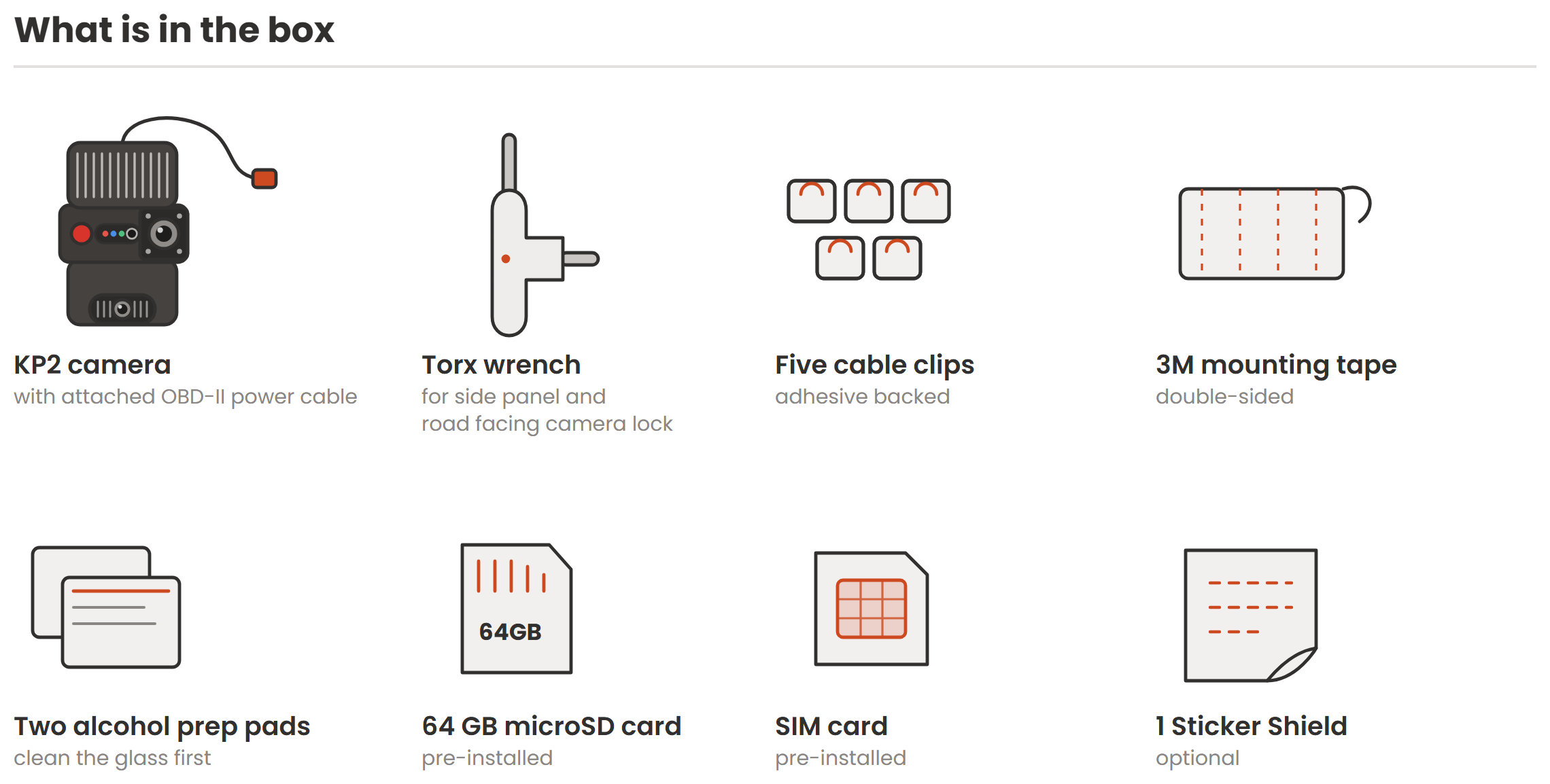
The KP2 is a dual-channel video telematics camera. It records the road ahead and when the optional driver facing camera is installed, the cab interior. This article covers the full installation from unboxing to a verified, calibrated device.
Allow about 15 minutes for the installation, plus time for routing the cable and running the verification check at the end.
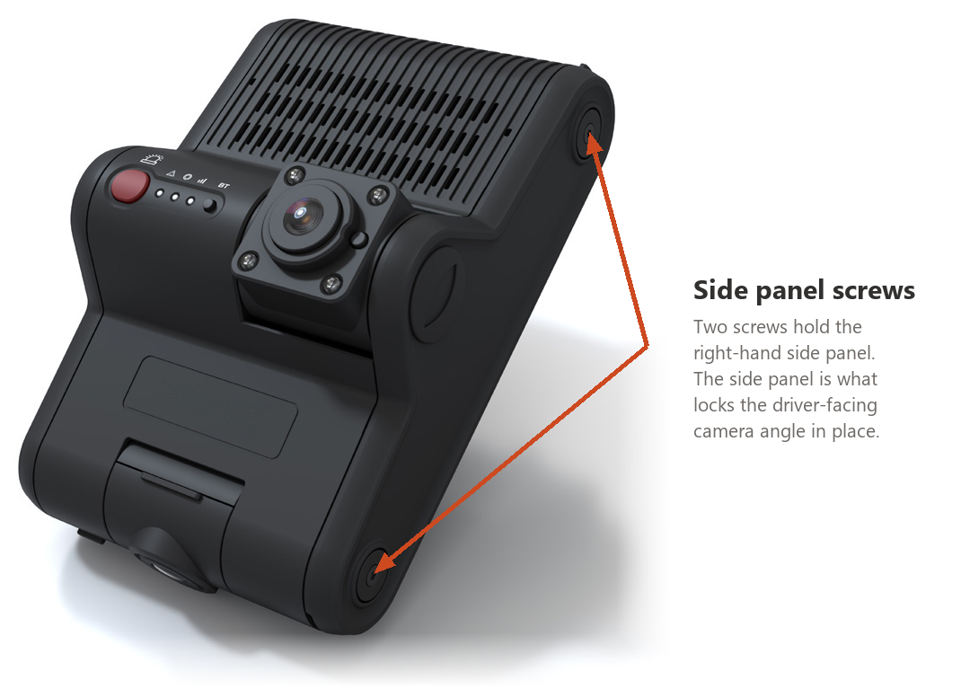
| Control | What it does |
|---|---|
| Large red button | Pressing it raises a panic event and flags the footage at that moment so it can be found later. |
| Small black button | G-sensor calibration. Press for 3 seconds and listen for the confirmation tone. Holding it down longer puts the device into Bluetooth pairing mode for the external panic button, where the red and blue lights blink. |
| Red light | The warning light. Off is healthy. Steady or blinking means a fault, and the pattern tells you which one. |
| Blue light | The record light. On means the device is recording. It blinks fast during shutdown. |
| Green light | The network light. On means the device has an LTE connection. After boot it is either on or off, so off is the fault. |
Blue and green on with red off is the healthy state. All three lights on together is the normal end of the boot sequence, not a fault. The full set of fault patterns is in Step 7 below, and in the KP2 status light and sound reference.
Check local law first. Windshield-mounted device rules vary by state, province and country. Confirm the placement you plan to use is compliant before you install the device.
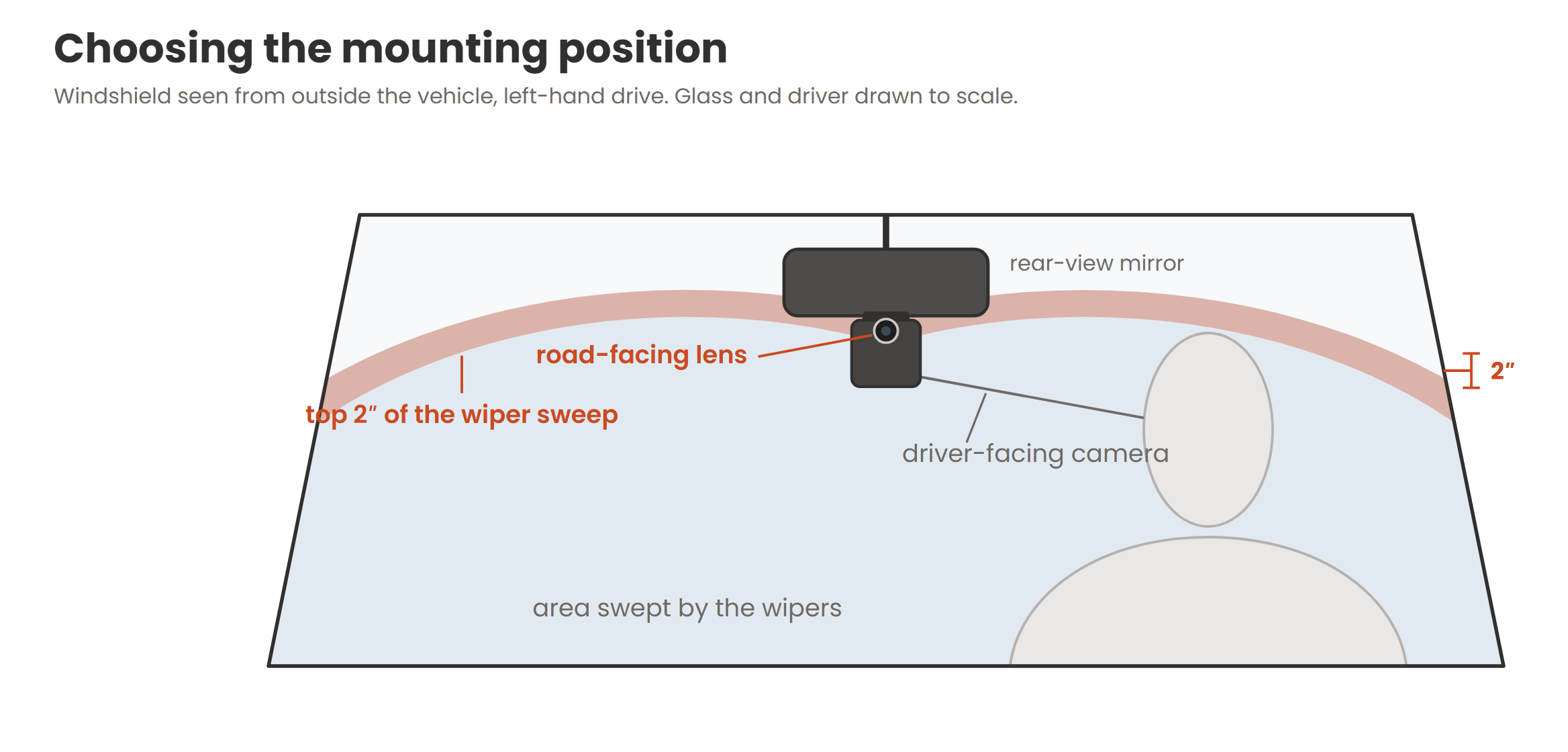
Mount the KP2 as close to the horizontal center of the windshield as the vehicle allows, high on the glass and behind the rear-view mirror shadow where possible. Centering the device keeps the road camera square to the direction of travel and keeps the mirror blind spot small.
The mounting position must satisfy all of the following.
Mount the road-facing camera as high in the wiper sweep as the vehicle allows, with the lens within the top 2 inches of the swept area. A clear lens in the rain is worth more than a perfectly centered mount. Federal rules for commercial vehicles allow the device up to 8.5 inches below the top edge of the swept area, so a lower position can still be compliant where 2 inches is not achievable. Confirm the placement against local regulations before applying the adhesive.
For a driver-facing installation the camera also needs to sit level with or slightly above the driver's eyes and nose, with a clear view of the face and minimal obstruction from the mirror, sun visor or A-pillar. The road-facing camera is aimed with its lens angle lock screw, so set the angle and tighten the screw once the bracket is mounted.
Position before you press. Dry-fit the camera and mark the spot before you apply the Sticker Shield. The Sticker Shield is what lets you remove and refit the device later, but the shield itself still needs to go on in the right place the first time.
Why the Sticker Shield. The bracket's 3M tape bonds to the Sticker Shield instead of the windshield, so the device can be removed and reapplied without ruining the adhesive or leaving residue on the glass. Refrain from trimming the sticker shield as the large surface area of the sticker allows the camera to remain fixed to the windshield.
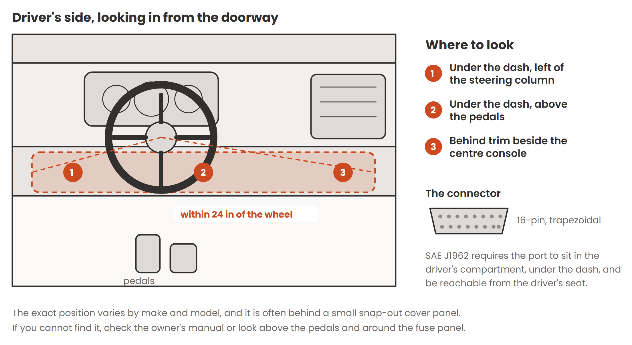
The KP2 is powered by the OBD-II adapter. It runs on 12 V or 24 V DC and draws up to 1.5 A, with power consumption around 4 W, rising to about 6 W with ADAS and driver monitoring enabled. The adapter handles all of that, so there is no wiring to do.
Splitter cables are available for heavy vehicles that use a JBUS diagnostic connector, so the adapter can share the port with existing equipment.
The OBD-II adapter is the only supported power connection. Do not hardwire the device and do not power it from a cigarette lighter socket.
Press for 3 seconds and release. Holding the calibration button down longer puts the device into Bluetooth pairing mode for the external panic button, where the red and blue lights blink. That is easy to mistake for a fault.
If the lights do not settle into blue and green on with red off after 5 minutes, the device is reporting a fault. The key patterns are listed below.
| Indication | Meaning |
|---|---|
| All three lights on, during the first moments after power up | Boot finished. Normal. |
| Blue on, green on, red off | Healthy. Recording and connected. This is the target state. |
| Red steady after boot has finished | Video loss on a camera channel. Check the driver camera seating and both lens covers. |
| Red blinking fast, blue off | SD card full. |
| Red blinking slowly, blue off | SD card error, no card fitted, or a write failure. |
| Red blinking slowly, blue still recording | Data network connection error, or a driver monitoring camera communication error. |
| Green off | LTE modem or SIM error. After boot the green light is either on or off, so off is the fault. |
| No lights at all with the ignition on | No power reaching the device. Recheck the adapter at both ends and the OBD-II port fuse. |
Camera aim drives the ADAS accuracy. Following distance and forward collision detection depend on what the road camera can see. A lens left badly aimed, or left loose in its mount, will produce alerts that fire at the wrong time for the life of the installation.
Run this check on every installation. It takes two minutes and catches the faults that otherwise come back as a support ticket a week later.
Need a hand with an installation? Contact Datablaze support! Make sure to include the IMEI which can be found on the device and a summary of the issue at hand.
Was this article helpful?
That’s Great!
Thank you for your feedback
Sorry! We couldn't be helpful
Thank you for your feedback
Feedback sent
We appreciate your effort and will try to fix the article